After all components are modeled and compiled they can be used in a system configuration and deployment model. In this scenario a robot should be controlled with a keyboard. To do so, a new SmartSoft Deployment Project has to be created and the following components have to be imported into the System Configuration:
SmartKeyboardNavigation
SmartPlayerStageSimulator
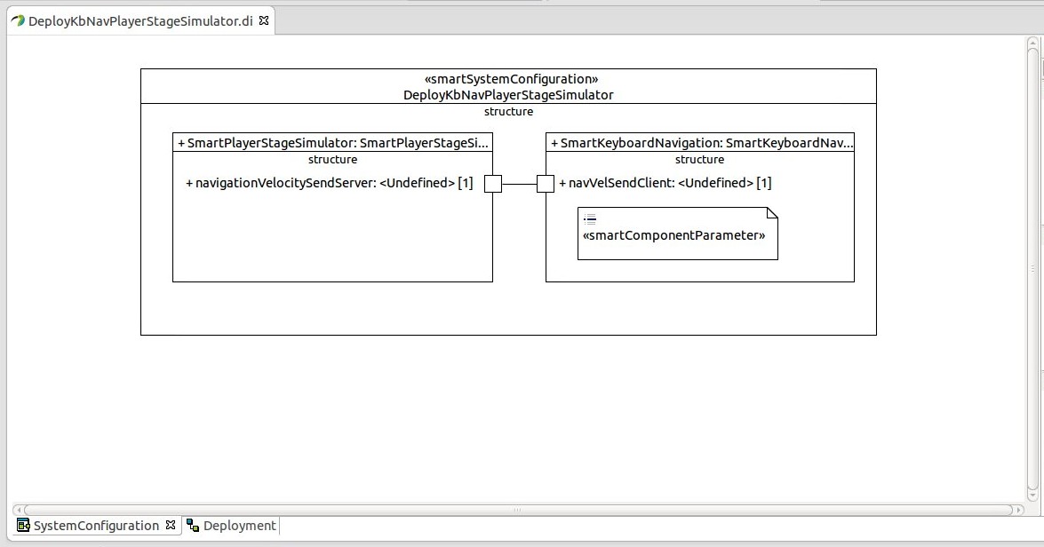
Instances of these components have to be created in the System Configuration. Additionally, the services
"navigationVelocitySendServer" of the SmartPlayerStageSimulator and
"navVelSendClient" of the SmartKeyboardNavigation
have to be enabled and connected. To be able to change the values of the parameters a SmartComponentParameter is added to the instance of the SmartKeyboardNavigation component. In this example the values are doubled.
	Param Settings {
		this.speedAcceleration = 300
		this.angularAcceleration = 0.4
	}
Figure 3.4 illustrates the modeled System Configuration.
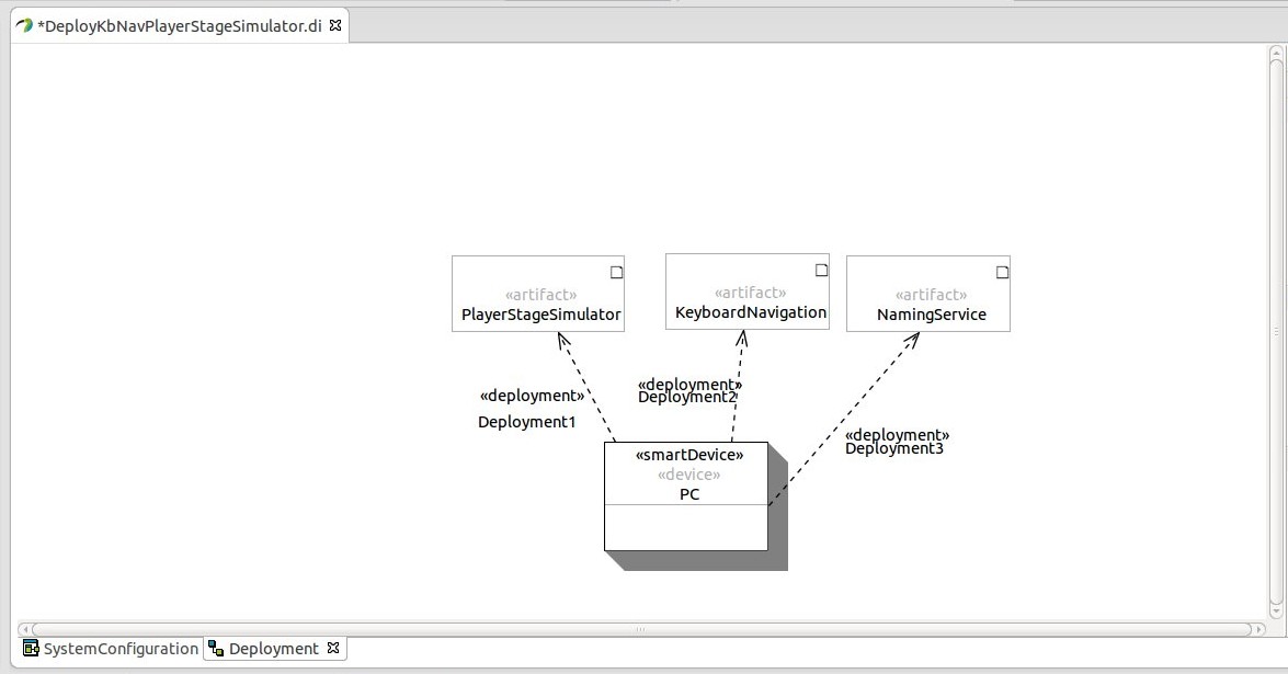
Additionally the Deployment has to be modeled. The Deployment contains the following elements:
SmartDevice (name: PC)
SmartNamingService (name: NamingService)
SmartArtifact (name: KeyboardNavigation, utilizedComponentInstance: SmartKeyboardNavigation)
SmartArtifact (name: PlayerStageSimulator, utilizedComponentInstance: SmartPlayerStageSimulator)
The Deployment is illustrated in figure 3.5.
After generating and deploying the the Deployment project, the scenario can be started. After the scenario is started the world (simulator) can be loaded by typing the corresponding number into the SSH window. The robot can be controlled with the arrow keys or the WASD keys. To do so, the commands have to be typed into the console window of the SmartKeyboardNavigation component.
In the previous scenario (section 3.2.3.1) the robot will hit obstacles if the user does not avoid these obstacles in time. To add obstacles avoidance, the following components have to be added to the System Configuration:
SmartCdlServer
SmartRobotConsole
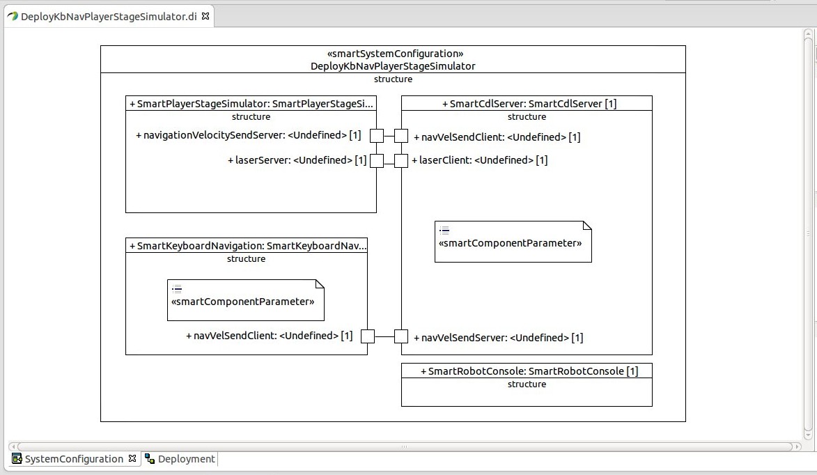
Instances of these components have to be added to the System Configuration. Additionally, the services
"laserServer" of the SmartPlayerStageSimulator and
"navVelSendServer", "navVelSendClient", "laserClient" of the SmartCdlServer
have to be connected. The services has to be connected as follows:
"navVelSendClient" (SmartKeyboardNavigation) - "navVelSendServer" (SmartCdlServer)
"laserServer" (SmartPlayerStageSimulator) - "laserClient" (SmartCdlServer)
"navigationVelocitySendServer" (SmartPlayerStageSimulator) - "navVelSendClient" (SmartCdlServer)
Additionally the parameter "plannerInit" of the SmartCdlServer component has to be set false, because no path planning is used in this scenario. Furthermore the parameter "dataDir" has to be adjusted, because additional files are necessary for this component. To adjust the parameters of the SmartCdlServer component, a SmartComponentParameter has to be added to the component:
Param server {
	this.plannerInit = false
}
Param cdl{
	this.dataDir = "./"
}
The resulting System Configuration is illustrated in figure 3.6.
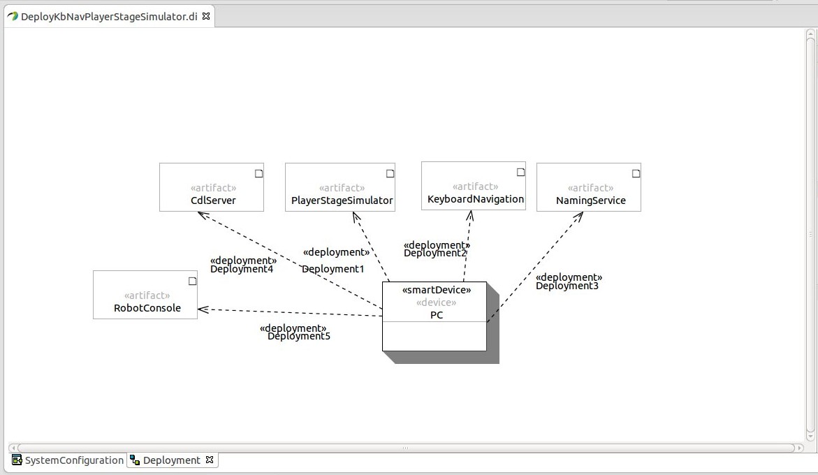
In addition the Deployment has to be adapted. Therefore, two additional SmartArtifacts have to be added:
SmartArtifact (name: CdlServer, utilizedComponentInstance: SmartCdlServer)
SmartArtifact (name: RobotConsole, utilizedComponentInstance: SmartRobotConsole)
Figure 3.6 shows the resulting Deployment.
After the code is generated the files
CDLacc_P3DX.dat,
CDLcontour_P3DX.dat,
CDLdist_P3DX.dat and
CDLindex_P3DX.dat
have to be copied from $SMART_ROOT/data/cdl/ to the generated DeployKbNavPlayerStageSimulator/src/SmartCdlServer_data folder. These files are required by the SmartCdlServer component (cdl lookup files). Now, the scenario can be started. After choosing a world (simulator) the number 99 has to be typed into the SmartRobotConsole window. To enable the control of the robot with a keyboard "Demo 4" has to be chosen afterwards by typing the number 4. The robot should now be moving controlled by the users keyboard input, however avoiding collisions with obstacles.